
OVERVIEW
Good tooling starts with better decisions.
Design and simulation support from part concept to frozen tool design.
2–5 days
DFM turnaround
NX / SW
Design platforms
Moldflow
Simulation
20+ yrs
Team experience
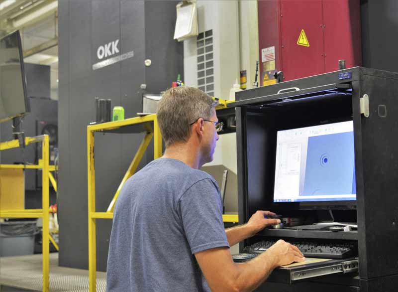
Most tooling problems are designed in long before the first chip is cut. Our engineering team reviews the part, simulates the process and freezes a design that can be built and measured.
We work in NX, SolidWorks, CATIA and Moldflow. Deliverables include DFM reports, filling/packing/cooling/warpage analysis, 3D tool design, 2D drawings, BOMs, fixture design and trial documentation. For legacy parts, we reverse-engineer from samples or scanned data.
Every project is assigned a project manager who coordinates design, machining, trial and shipping. Weekly progress reports keep your team informed, and design changes are documented before they reach the floor.
✓ Part and draft review before tool design
✓ Mold flow for filling, cooling and warpage
✓ 3D tool design and 2D drawings
✓ Reverse engineering from samples
CAPABILITIES
What we deliver
Practical capabilities, matched to the tooling and the production volume — not a generic menu.
01
DFM review
Draft, wall thickness, radii, gate location, ejector marks and tolerance stack-up.
02
Mold flow analysis
Filling, packing, cooling and warpage simulation with practical recommendations.
03
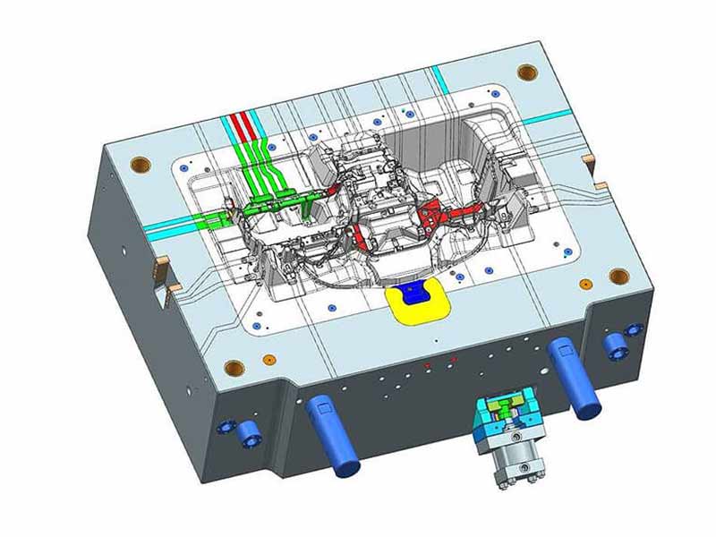
3D tool design
Full 3D tool assembly, cavity/core splits, slides, cooling and ejection.
04
2D drawings & BOM
Manufacturing drawings, bill of materials and steel/component specifications.
05
FEA & structural checks
Load, deflection and fatigue checks for tooling, fixtures and lifting points.
06
Reverse engineering
Scan or sample measurement, CAD reconstruction and design-for-manufacture review.
SPECIFICATIONS
Typical range and tolerances.
Every project is quoted against the part, material and inspection requirement. Values below are typical starting points — we confirm the exact capability for your drawing.
Deliverable
DFM report, mold flow report, 3D design, 2D drawings
Software
Siemens NX, SolidWorks, CATIA, Moldflow
DFM turnaround
2–5 working days
Design review
Customer approval before manufacturing
Documentation
BOM, steel list, trial report, dimensional report
Project management
Weekly progress report and single point of contact
MATERIALS & TOOLING
Materials we work with
NX · SolidWorks · CATIA · Moldflow · AutoCAD · Geomagic · STEP / IGES
Documentation
✓ Material certificates on request
✓ Dimensional report with critical dimensions
✓ Trial report and process parameters
✓ 2D drawings and spare-part list
PROCESS
How the project runs
A named project manager, weekly reporting and documented sign-off at each stage.
01
Review
Part data, volume, material and process requirements.
02
Simulate
DFM and mold flow, with clear recommendations.
03
Design
3D tool design, drawings, BOM and design freeze.
04
Support
Manufacturing, trial and change-management support.
GALLERY
From the floor
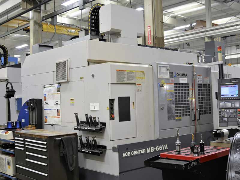
Representative tooling, machining and inspection work from our Kunshan facility.
FAQ
Questions, answered.
What files do you need for a DFM review?
A STEP or IGES model is preferred; 2D drawings, resin/material, annual volume and critical dimensions help us give specific feedback.
Can you review a design from another supplier?
Yes. We provide independent DFM and mold-flow reviews, and can take over the tool design or manufacturing.
Do you charge for DFM?
Initial feasibility feedback is free. Detailed mold-flow studies and full tool design are quoted as part of the project.
Can you reverse-engineer a part with no CAD?
Yes. We scan or measure the sample, reconstruct the CAD model and review it for manufacturability before tooling.
START A PROJECT
Have a mould project in mind?
Send us your part data and requirements. We will reply with a DFM review and a clear quotation within 24 hours.